A wiring detector usually consists of a sensor, which is also an antenna that receives an alternating electric field, an amplifier and an indicator. For a proper capacitive antenna, the amplifier must have a huge input impedance; for this, a variant with a source follower on a field-effect transistor is usually used.
The design is made using ultra-sensitive BC547 transistors. In the role of a 6V power supply for the circuit, I used a dead Krona battery from a multimeter. But in principle, you can also use a standard lithium battery from an old mobile phone or navigator.

If BC547 transistors cannot be found, then domestic KT315 can also be used. For more details on assembly, see the video instructions just above.
The peculiarity of this wiring finder circuit is that it not only looks for an electromagnetic field, but is also able to measure the oscillation frequency of the electric current flowing through it. The selection of a frequency of 50 Hz in the search allows you to cut off all possible interference and is carried out by the PIC 12F629 DD1 microcontroller. The signal caught by the antenna enters an amplifier using transistors, which has a high gain and input impedance.

The collectors of the KT3102 transistors are connected to the TMR0 timer input, pin 5 of the microcontroller. In addition, in the circuit of the hidden wiring detector, in addition to the sound indication, there is a toggle switch to turn on the light alarm when the device is turned on. Capacitance C2 is used to protect the input from possible interference.
The microcontroller counts the periods of the alternating voltage generated by the sensor over a certain period of time. When the circuit detects a 50 Hz signal, it beeps. During the beep, the HL1 LED goes out. This is a simple scheme, all that remains is, and download the firmware a little higher (See folder 011-el in the archive).
The antenna sensor is made of a 20 mm diameter ring of insulated mounting wire, and is connected by a shielded wire to the input of the circuit.
The signal from the sensor arrives at pins 8 and 9 of the K176LA7 microcircuit and DD1.1 goes into linear mode due to negative feedback through resistances R1 and R2. Capacitance C2 and variable resistance R2 allow you to adjust the depth of feedback by changing the input resistance and sensitivity of the circuit.
Capacitance C1 is used to eliminate self-excitation of the amplifier. The output of element DD1.1 is connected to the inputs DD1.2 DD1.4. The signal amplified by the K176LA7 microcircuit passes through the SZ capacitor to connector X1, to which high-impedance headphones are connected.

In the second circuit, the sensitivity is adjusted by capacitance C1, and the sound emitter is a piezo emitter connected via a bridge circuit.
Variable capacitor C1, see figure three, is made from printed circuit board conductors. The dielectric gasket of the capacitor can be made from photographic film, with the emulsion layer removed. The spring can be borrowed from a fountain pen.
Several, albeit outdated, but still relevant schemes with an emphasis on the novice radio amateur
Drilling a hole for a dowel screw or nail in the wall is not difficult. The main thing is that when perforating, do not stumble upon hidden wiring and damage it. A hidden wiring detector helps detect a break or a live electrical cable in the wall. In order not to spend extra money, we will construct a simple detector based on the K561LA7 microcircuit, and talk about the selection criteria and advantages of factory-made devices.
Homemade detector with a piezoelectric element - simple words about the complex
Hidden wiring detectors are divided into low and high class devices. A low-class device is designed to search for electrical appliances and live wiring. A high-class detector has greater sensitivity and advanced functionality. Such a device is used to determine the breakage of hidden wiring and detects the location of wires without voltage.
You can make a hidden wiring detector with your own hands from available materials by purchasing several small parts. When designing this device, keep in mind that it is suitable for detecting live wiring in a wall. And if you need high-frequency equipment to detect a break and the exact location of a cable down to the millimeter, purchase a high-quality detector in the store.
To assemble the device you will need the following set of elements:
- microcircuit K561LA7;
- 9 V Krona battery;
- connector, battery connector;
- current limiter (resistor) with a nominal resistance of 1 MΩ;
- sound piezoelectric element;
- single-core copper wire or wire L= 5–15 cm;
- wiring for soldering contacts;
- a wooden ruler, a power supply box, or another homemade structure for laying the chain.
Additionally, for work you will need a low-power soldering iron up to 25 W, so as not to overheat the microcircuit; rosin; solder; wire cutters Before we begin assembly, let's take a closer look at the main elements. The main part on which the assembly takes place is a Soviet-type K561LA7 microcircuit. It can be found on the radio market or in old stock. The K561LA7 microcircuit is sensitive to static and electromagnetic fields created by electrical devices and conductors. The current level in the system is controlled by a resistor, which is located between the integrated circuit and the antenna. We use single-core copper wire as an antenna. The length of this element affects the sensitivity of the device and is selected experimentally.
When selecting the length of the copper wire, ensure that it only responds to the electrical cable. This will allow you to determine the exact location of the wiring in the wall.
Another important assembly detail is the piezoelectric element. Catching an electromagnetic signal, it creates a characteristic crackling sound, which signals the presence of wiring in a given location. It is not necessary to specifically purchase the part; take out the speaker from an old player or toy (Tetris, Tamagotchi, watch, sound machine). Instead of a speaker, you can solder headphones. The sound will be cleaner and you won't have to listen to the crackling noise. As an indicator of hidden wiring, you can additionally install an LED element into the device. The circuit is powered by a 9-volt Krona battery.

To make it more convenient for you to work with the microcircuit, take cardboard or foam plastic and mark with a needle the places for attaching the 14 legs (legs) of the part. Then insert the legs of the integrated circuit into them and number them from 1 to 14, starting from left to right with the legs facing up.

We make connections in the following sequence:
- 1. Prepare a box where we will place the parts after assembly. For a cheap alternative, use a plastic bottle cap. Make a hole in the end with a knife with a diameter of about 5 mm.
- 2. Insert a hollow rod into the resulting hole, for example, the base of a ballpoint pen, suitable for the diameter, which will serve as a handle (holder).
- 3. Take a soldering iron and solder a 1 MΩ resistor to pin 1–2 of the microcircuit, covering both contacts.
- 4. Solder the first wire of the speaker to the 4th leg, after which we close the 5th and 6th legs together, solder them and connect the second end of the piezoelectric element wire.
- 5. We close legs 3 and 5–6 with a short wire, forming a jumper.
- 6. Solder the copper wire to the end of the resistor.
- 7. We pull the wires of the connector (battery connector) through the handle. We solder the red wire (with a positive charge) to leg 14, and the black wire (with a negative charge) to leg 7.
- 8. From the other end of the plastic cap (box) we make a hole for the copper wire to exit. We place a microcircuit with wiring inside the lid.
- 9. Close the lid on top with the speaker, fixing it on the sides with hot glue.
- 10. Straighten the copper wire vertically and connect the battery to the connector.
The wiring detector is ready. If you have connected all the elements correctly, the device will work. If possible, we recommend equipping the system with a switch or removing the battery from the connector after finishing work in order to save power and not overload the system.
A device with an LED is the second option for assembling the system
The simplest device for finding hidden wiring with an LED indicator is assembled according to a similar scheme. To assemble the system you will need: an LED, a 9 V Krona battery, thin wires, a copper wire (5–15 cm), a connector for the battery (connector), a connector for the microcircuit and the K561LA7 microcircuit itself. The set of tools is unchanged - low power soldering iron, rosin, soldering, wire cutters.

We solder the antenna (copper wire) so that it closes pins 1 and 2 of the microcircuit. We close legs 3, 5, 12 and 13 together, first soldering the horseshoe loop. After this, we make a jumper from the wires for legs 4, 8 and 9. Next, we connect the LED, an indicator of hidden wiring, with a positive charge to the 14th leg, and a negative charge to the 7th leg. We solder the battery connector (connector) (–) to the 7th leg, and (+) to the 14th leg. We close the assembled K561LA7 microcircuit with the connector, first bending the legs inward. We insert the battery into the connector and check the device. When the detector antenna is brought close to hidden wiring, the LED lights up. To make the device more neat and convenient, place the assembled circuit in a box, for example, from an old power supply, making the necessary holes for the output if necessary.
Groups of detectors - types and purpose
All detectors for detecting wiring are divided into 4 types: electrostatic, electromagnetic, metal detectors, combined (universal) types. Let's look at each group.
Electrostatic devices belong to the budget class. They are easy to use, but have a small range of capabilities and are only suitable for detecting live wiring. Also, the device often malfunctions, reacts sensitively to the presence of foreign metal objects in the wall, and operates in a humid environment. This device is optimal for searching for wiring in an apartment. In damp rooms (bathrooms, basements, balconies, bathhouses), the quality of the electrostatic detector will be extremely low.
Electromagnetic detectors are of higher quality and more reliable in operation. Such devices are used to search for de-energized wiring and at low voltage, although errors cannot be excluded. To obtain accurate readings, the load in the circuit when operating electromagnetic detectors should be about 1 kW.

Metal detectors are also used to detect wiring inside walls. However, their main problem is that the wiring finder reacts to the presence of all metal objects, be it a nail or a screw, which is why the accuracy of the device in detecting the exact location of the wiring is reduced. Detecting hidden wiring without voltage using a metal detector gives good results. The signal is given by sound or a flashing LED.
The most accurate results are obtained with combined (universal) models that combine the functions of all previous devices. Universal detectors allow you to find out not only about the location of the wiring, but also its depth, the type of metal in the wire strands, and the presence or absence of voltage. Multidetectors belong to a series of combined options. In addition to wires, they find plastic pipes, wooden elements and non-ferrous metal structures in the wall.
Choosing a device in a store – what to look for?
To decide which detector is better, we present the main characteristics by which the device is divided into quality and functionality. When choosing a device for detecting hidden wiring, pay attention to:
- scanning depth;
- type of signal (sound or color);
- the ability to detect a break;
- difference in types of structures and wiring in the wall.
Scanning depth is one of the main indicators of a quality device. The budget determinant reacts to the location of hidden wiring at a depth of 1–2 cm or, in other words, the occurrence of wiring under a layer of plaster. This indicator is not enough for working at home, so for correct operation we recommend purchasing a detector that scans wiring in the wall to a depth of 5–6 cm. Wires in apartments and private houses are rarely laid deeper, so you should not overpay for this parameter.

When choosing the type of signal, give preference to combined options with a sound and color signal. This choice allows you to reduce errors to a minimum. Pay special attention to the transmission of the sound signal, choosing devices with a change in tone. As the detector approaches or moves away from the wiring, the sound melody changes from low to high and vice versa. If you need accuracy, choose a detector with an LCD display, it allows you to locate hidden wiring with details. Information is displayed on the screen in the form of icons and bars. Regardless of the type of device, it must be tested before purchasing.
When choosing a simple design for one-time work, focus on purchasing an electromagnetic detector. The indicator screwdriver is a classic example of such a device. For correct operation, use contactless battery-powered devices that can pick up weak signals. The appearance of an indicator screwdriver does not affect its quality, but only its convenience. This device is suitable for detecting hidden wiring under a thin layer of plaster. For searching in concrete and brickwork, look for other options.
In addition, the electromagnetic device is not suitable for use in damp rooms and conditions. If this parameter is important to you, consider purchasing a universal device. Such detectors have advanced functions, we recommend that you familiarize yourself with them. You may not need full functionality, so before buying expensive devices, consider the purpose of use. For one-time work, an indicator screwdriver or a simple electrostatic device is sufficient. In professional daily activities, you cannot do without a universal device.
Bosch, Black&Decker detector - a brief overview of popular series
If you are looking for a high-quality, middle-class device for hidden wiring, experts recommend Bosch detectors. Among the series of this manufacturer, the Bosch GMS 120 Prof model is distinguished. What makes it special? It has a deep scanning, about 12 cm, detects metal objects (copper, steel, ferrous metal), live wiring, wood, plastic pipes. Wide functionality allows you to select scanning material. A signal about the location of the desired item is given by sound and color. Additional functions include the ability to mark points for perforation in the wall. Bosch GMS 120 Prof runs on regular batteries. The main advantages of the device: simple interface, convenient adjustment of control modes, point measurement, complete display of information about the object and deep scanning.

Black&Decker devices are also widely used among craftsmen for detecting hidden wiring and searching for dissimilar materials, with the exception of wood. Consider the BDS200 model. It has mode adjustment, which allows you to control the sensitivity of the device, and a shockproof housing. Black&Decker BDS200 is equipped with a sound and color signal, which is displayed on the device display.
Woodpecker device – what does the Russian manufacturer offer?
To determine hidden wiring, technicians use a device from the domestic manufacturer Dyatel. Three main advantages of the detector: quality, affordable price, availability of basic functions for operation. How does the device work? The device reacts to the predominance of the electrostatic field; when it hits resonance, the device emits a sound signal, which intensifies as it approaches the hidden wiring. However, the device only detects vibrations coming from the live wire. The Woodpecker detector does not detect a de-energized cable. The device has a built-in regulator and a self-monitoring mode that controls the sensitivity of the detector. The device is lightweight, weighing no more than 250 g. The detector is suitable for determining:
- hidden wiring in all ceilings (walls, ceiling, floor);
- broken wiring;
- correct connection of the electric meter circuit, without removing seals and terminal blocks;
- phase wire;
- voltage in the contact network;
- ungrounded installation;
- electromagnetic fields created by household appliances;
- correct operation of fusible parts and fuses.
In order for the purchased detector to please you with stable operation, we take into account the following features. The wiring is laid in a vertical and horizontal position. To make the search for hidden wiring faster, we move in these directions. At the point with the highest signal level we put a mark and move the antenna a little further from it. The electrical cable is located between the two points. If the signal has the same intensity throughout the entire area, it is possible that, in addition to the electrical cable, there is a metal structure in the ceiling, for example, a sheathing. To reduce sensitivity, place your hand against the wall.
During apartment renovations, especially in old houses, an electrical wiring diagram is required. Otherwise, when drilling holes or tapping, you can damage hidden wires that are energized.
Important! Regardless of whether you know where the wiring is located, work in the room should be carried out during a power outage.
A metal and hidden wiring detector is used for searching.
Such a device can be purchased at a power tool store. This is essential equipment for repair teams. However, if you are simply renovating your apartment over a period of several years, the cost of purchasing it is irrational. The design of the device is simple. A craftsman who knows how to hold a soldering iron can make a wiring detector with his own hands. In this case, its value will tend to zero.
How to make a wiring detector yourself?
There are two main concepts:
- Voltage multiplication principle;
- A radio receiver on a microcircuit that detects an electromagnetic field.
Both designs are easy to manufacture and are assembled using accessible components. If you are into electronics, you can pick up radio components in your workshop. Even if you buy them on the radio market, the cost is incomparable with a factory sample.
Determinant of hidden wiring on transistors
Components for manufacturing:
- A multistage voltage multiplier will require ultra-sensitive transistors. BC547 has proven itself well. These are silicon miniature bipolar triodes, with an n-p-n structure. They have a fairly high gain with minimal noise;
- Low power resistors. 1Mohm, 1kOhm and 220Ohm. For the first, second and third cascade, respectively;
- Indicator LED;
- Batteries or accumulators;
- Frame.
Schematic diagram of the device:

The first stage receives a weak signal from the antenna, shown in the diagram with an arrow. It is an electromagnetic field created by electrical wiring.
Tip: To increase the search efficiency, it is recommended to plug in a low-power electrical appliance that creates interference, for example, a room fan.
A small current appears at the emitter, which is repeatedly amplified by the second stage. The almost finished signal is fed to the base of the third transistor (cascade). After amplification, an electric current sufficient to light up the LED is generated at its emitter. The device is powered by 6 volts.
Industrially produced detectors are often combined - they contain several types of detectors:
·
Electrostatic. Pros – simple, long detection range.
Cons – they don’t work on damp walls (they show that the wiring is everywhere). Requires voltage in the wiring.
·
Electromagnetic. Pros – simple, good detection accuracy.
Cons - they require not only the voltage in the network, but also that the wire be loaded with a powerful load, usually on the order of kilowatts.
·
Metal detectors. They're just looking for metal in the walls. Pro – you can search without voltage.
Cons: complicated, foreign metals interfere. If a nail is hammered somewhere nearby, then nothing good will come of it.
Hidden wiring indicators
Resistor R1 is needed to protect the K561LA7 microcircuit from increased voltage of static electricity (as practice has shown, it does not need to be installed). The antenna is a piece of copper wire of any thickness. The main thing is that it does not bend under its own weight, i.e. was quite tough. The length of the antenna determines the sensitivity of the device. The most optimal value is 5...15 cm. When the antenna approaches the electrical wiring, the detector emits a characteristic crackling sound.
The device is convenient for determining the location of a burnt-out lamp in a Christmas tree garland - the cracking stops near it. The ZP-3 type piezo emitter is connected in a bridge circuit, which provides increased volume.
 In Fig.2 shows a detector with sound and light indication.
The resistance of resistor R1 must be at least 50 MOhm. There is no current-limiting resistor in the VD1 LED circuit; the DD1 microcircuit (K561LA7) copes well with this function itself.
HIDDEN WIRING INDICATOR DIAGRAM.

Details:
- C1...C5 - 10 µF;
- VT1 - KT209x or KT361x;
- VT2 - KP103x;
- VT3 - KT315x, KT503x or KT3102x;
- R1 - 50K…1.2 M;
- R2 - 150…560 Ohm;
- Antenna 80…100mm.
Device for detecting hidden wiring
 The circuit is powered by 3-5 V. The circuit runs on two watch batteries continuously for about 6 hours. The antenna is a coil wound with 0.3 or 0.5 mm wire on a 3 mm frame. The reel can be used both on a frame, in the form of a rod, and in a frameless form.
Depending on the thickness of the wire, a certain number of turns are wound, with wire 0.3 mm - 25 W, 0.5 mm - 50 W.
The setup comes down to selecting resistor R1*; it adjusts the maximum volume of the main phone, depending on its resistance.
In the circuit, instead of the KP103 field-effect transistor, you can use KP303D.
A device for detecting breaks in electrical wiring.
 The following device can be easily placed in a marker, the antenna can be pulled out through the hole for the rod, the length of the antenna is 5-10 cm, if you need a sensitivity of no more than 5 - 10 cm, then the length of the gate of the field-effect transistor is sufficient for the antenna.
Field-effect transistor VT1 (Fig. 1) acts as a sensor that “captures” even very weak electric field strength. Therefore, when the finder field-effect transistor is near the phase wire of the lighting network, the resistance of its drain-source section will decrease so much that transistors VT2, VT3 will open. LED HL1 will flash. The field-effect transistor can be any of the KP103 series, and the LED can be from the AL307 series. Bipolar transistors can be any low-power silicon or germanium structure indicated in the diagram and with the highest possible current transfer coefficient. Resistors - MLT-0.125. Transistor VT2 (KT203) can be replaced with KT361. When mounting a field-effect transistor, it is placed horizontally on the board, and the gate lead is bent so that it is above the transistor body. If during operation of the finder it is revealed that it is excessively sensitive, the shutter lead is shortened.
A simple contactless probe.
Only two elements - the DD1 microcircuit and the HL1 LED - make up the circuit of this probe; the K176LP1 microcircuit contains three p and three n-channel CMOS transistors. By connecting the pins of the microcircuit in such a way as to form a chain of three inverters, you can get a device that fairly well amplifies the currents induced by the alternating voltage field in the phase wire of the power network.
An LED is turned on between the output of the last inverter - pin 12 of DD1 and the plus of the probe power supply. It lights up when a phase network wire is placed close to pin 6 of the microcircuit.
The LED will go off if, by running the probe along the faulty wire connected to the electrical network, you reach the break point.

Combining inverters into a chain must be done by connecting the following DD1 pins:
1. Option for connecting the microcircuit pins: 3, 8 and 13; 2 and 10; 4, 7 and 9; 1 and 5; 11 and 14.
2. Option for connecting the microcircuit pins: 3,8,10 and 13; 1, 5 and 12; 2.11 and 14; 4,7 and 9.
The sensitivity of the probe is such that it does not necessarily need to touch the insulation of the wires being tested. The current consumption does not exceed 3 mA - at a battery voltage of 4 -5V.
The length of the conductor - the “probe” of the probe leading to pin 6 of the microcircuit should be no more than 15 - 20 mm. The switch in the probe is optional, since in non-operating mode the circuit consumes a negligibly small current, due only to the static current in the CMOS transistors of the inverter chips.
Hidden wiring finder circuit - alternating electric field indicator

A simple indicator of an alternating electric field of hidden wiring can be assembled using a voltage divider - resistor R1 and a field-effect transistor channel - as a voltage divider controlled by an external electric field. A generator based on the K122TL1 microcircuit was used as a controlled pulse generator. The generator load for indication is high-impedance headphone type TON-1 (TON-2)
In the presence of an external alternating electric field, the signal induced by the antenna is supplied to the control electrode of the field-effect transistor (gate), which causes modulation of the resistance of the field-effect transistor channel. As a result, the voltage drop across the divider changes, which, in turn, causes generation to occur with a changing frequency.
Indicator of hidden wiring on microcircuits
The circuit consists of an AC voltage amplifier, the basis of which is the operational amplifier DA1, and an audio frequency oscillation generator assembled on a Schmitt trigger DD1.1 (K561TL1), a frequency-setting circuit R7C2 and a piezo emitter BF1.
When the WA1 antenna is located close to the phase wire of the power supply network, the pickup of the EMF at an industrial frequency of 50 Hz is amplified by the DA1 microcircuit, as a result of which the HL1 LED lights up. This same op-amp output voltage, pulsating at 50 Hz, drives the audio frequency oscillator.
The current consumed by the device microcircuits when powered from a 9V source does not exceed 2 mA, and when the HL1 LED is turned on - 6...7 mA.
The WA1 antenna is a foil pad on a board measuring approximately 55x12 mm.

The circuit board is placed in a housing made of dielectric material so that the antenna is in the head part and is as far as possible from the operator’s hand. On the front side of the case there is a power switch SA1, an LED HL1 and a sound emitter BF1.
The initial sensitivity of the device is set by trimming resistor R2. An error-free installed device does not require adjustment.

The signal from an antenna 200 mm long is fed to the operational amplifier DA1 K140UD7. From output 6 DA1, the amplified signal is supplied to the rectangular pulse shaper DD1 K561LA7 and then to the output stage VT1, lighting the HL1 LED. It is advisable not only to see, but also to hear this signal. It is not advisable to connect the sound emitter in parallel with R5, HL1. For sound, a multivibrator is used on the KR1006VI1 timer. Capacitors C1, C2 select a pleasant sound and its duration, as well as the glow of the HL2 LED. In this version, the sound frequency is 1.7 kHz.
Depending on the insulation and the depth of the wires in the wall, the sensitivity can be changed by touching the common wire with your hand through a small capacitance capacitor SZ 27...33 pF, without bringing the device to self-excitation. With a larger capacity, the device will be excited.
The device is powered by 3 AA batteries connected in series with a total voltage of 4.5 V. When using the device, it is necessary to turn off powerful sources of the electric field: transformers, televisions, fluorescent lamps. A piezo emitter from telephone sets is used as a sound emitter.
LEDs HL1 - green, HL2 - red.
Device for detecting damage to hidden electrical wiring

The device is powered by an autonomous 9v source and is housed in an aluminum case measuring 80x38x27 mm.
Principle of operation:
One of the wires of the hidden electrical wiring is supplied with 12V alternating voltage from a step-down transformer. The remaining wires are grounded. The device turns on and moves parallel to the wall surface at a distance of 5...40 mm. In places where the wire is broken or terminated, the indicator goes out. The device can also be used to detect core damage in flexible cables and hose cables.
Hidden wiring detector
The device will save you from the possible risk of hitting a wire with a drill when drilling a hole in the wall, it will allow you to trace the path of the wire and in many other cases when it is necessary to detect hidden wires.
A piece of wire or a metal rod with a diameter of about 5 mm and a length of 70...90 mm is used as a sensor.
The principle of operation of the circuit.
A low-frequency multivibrator is assembled using bipolar transistors VT1 and VT3. Its operating frequency is determined mainly by the capacitor ratings, which are aluminum, niobium or tantalum electrolytic capacitors.
In the initial state, when the antenna probe of the device is removed a considerable distance from the hidden wiring, field-effect transistor VT2 is in cutoff mode. In this case, across resistor R4, which is connected to the source circuit of transistor VT2 (KP103D), a voltage drops approximately equal to 3.5 volts. In this case, the potential of the VT3 base is fixed at a level that keeps VT3 in a saturated state and the LED glows continuously. Transistor VT1 is in cutoff mode at this time. 
When the antenna probe approaches the place where the wire is hidden, where an alternating potential of 220V is maintained, the electrical component of the electromagnetic field of the network wire induces an alternating potential equal to hundreds of millivolts-units of volts at the antenna input. In this case, the corresponding half-cycles of the input signal open VT2, the current through resistor R4 increases, and therefore the voltage drop across it increases. The potential of the base of VT3 relative to the emitter of VT3 becomes low, putting VT3 in cutoff mode.
As a result, the LED begins to blink, indicating the presence of hidden wiring in this place.
RADIOAMATOR 11"2001
HIDDEN WIRING FINDER
When a 50 Hz signal is detected, the LED will flash at a frequency of approximately 1.56 Hz and the audio signal will be interrupted at the same frequency.
Let's look at the diagram (Fig. 1).
 Antenna W 1 - piece of installation wire about 25 cm long, located along the perimeter of the narrow side part of the device body. On transistors VT 1 and VT 2 a simple amplifier is made - a logic pulse former. It amplifies the signal induced in the antenna and feeds it to the meter D 1 (input “C”). From the number of outputs of a multi-bit counter K561IE16 analogue 4020BEY( D 1) only the output with the weighting coefficient “16” is used. That is, the state of this output changes every 16 input pulses, which means the frequency division is 32. Thus, when receiving a signal with a frequency of 50 Hz, the frequency here will be 1.5625 Hz. The LED will blink at this frequency. H.L. 1, connected to this meter output through an intermediate transistor switch - current amplifier ( VT 3) to make working with the device easier, there is a sound alarm made on a microcircuit D 2. This is a multivibrator circuit that produces pulses with a frequency of about 2000 Hz. On the elements D 2.1 and D 2.2 the multivibrator itself was made, and the elements D 2.3 and D 2.4 form a voltage amplifier that raises the potential difference between the terminals of the piezoelectric sound emitter B.F. 1 is twice the rated voltage of the logic one level.
The multivibrator is controlled - for it to work you need to apply logic one voltage at pin 13 of element D 2.1. Thus, the sound is turned on simultaneously with the indicator LED turning on. The device is powered by a 9-volt Krona battery. Switch S 1- button without fixation. When you are looking for wiring, you need to keep it pressed, release it, and turn it off (this was done to save battery). Sound emitter B.F. 1 - from a faulty multimeter. The printed plate is located above the chip D 2 (glued).
The K561IE16 counter can be replaced with almost any binary CMOS counter that has an output with a weighting coefficient of “16”. This could be K561IE20, K176IE1, or two counters of the K561IE10 chip connected in series. But in any case, the printed circuit board will need to be redesigned.
The printed circuit board is shown in Figure 2.
The board contains all the parts except the antenna and power supply. No setup required.
BINARY HIDDEN WIRING FINDER
The probe circuit consists of a probe-antenna, a transistor amplifier-pulse shaper and a counter with an indicator LED at the output.
 The antenna picks up the electromagnetic field, and pulses appear at the output of the amplifier stage at VT1 and VT2, the frequency of which is equal to the frequency of the input signal. If this is a wiring signal, then, of course, the pulse frequency will be 50 Hz. If it is a radio signal, then the pulse frequency will be much higher.
The probe works like this:
When the electromagnetic field emitted by the electrical wiring arrives at the antenna, pulses with a frequency of about 1.56 Hz appear at the meter output, and the indicator LED flashes evenly at the same frequency. If, however, a radio signal is received at the antenna, the frequency of which is significantly higher than 50 Hz, the LED blinks much faster and this is visually perceived as its constant glow with a slightly reduced brightness. Or, it does not light up at all, since the K561 series microcircuit may not allow a signal of too high a frequency to pass through.
To tune out weak but highly interfering radio signals, there is a variable resistor R1, which can be used to adjust the sensitivity of the probe input.
The device is powered by Krona, a small-sized 9V battery.
 The probe is made in the form of a miniature device housed in a suitable housing.
The antenna is a piece of winding wire with a diameter of about 1 mm and a length of about 30 cm, which is wound turn to turn on the front of the housing and secured.
Variable resistor R1 is made from a tuning resistor, with a homemade handle (from a plastic thumbscrew).
Practically no adjustment is required, only if the size of the antenna is selected.
WIRING FINDER
The peculiarity of this wiring finder is that it not only shows the location of electrical wiring, but can also estimate its depth, and also allow you to detect a radio bug or other device transmitting or emitting radio waves. With its help, you can determine which part of the wiring is more loaded and which is less loaded.
Circuit diagram 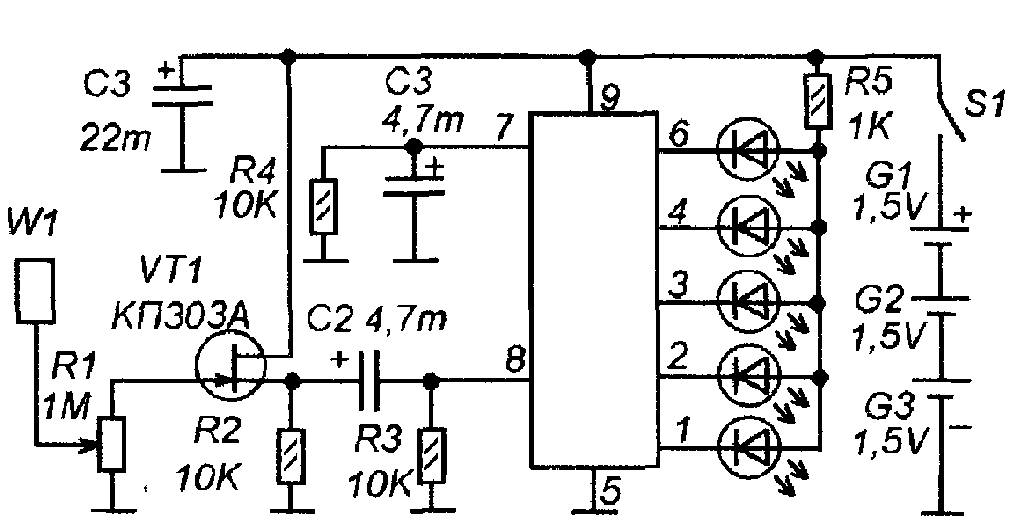 shown in the figure.
Antenna W 1 is a tin plate measuring approximately 60x60 mm. The plate is connected to the input through a variable resistor R1, which can be used to adjust the sensitivity level of the device. Transistor VT 1 has a cascade that increases the input resistance of the device. The alternating interference voltage from its output through capacitor C1 is supplied to an alternating voltage level meter made on the DA1- chip AN 6884(KA2284), switched on according to a standard circuit.
The voltage level of network interference is indicated on a scale of five LEDs HL 1-HL 5 - A L307.
The device is assembled in the housing of a faulty remote control for the Orion -688 video player. The battery consists of three “AA” cells with a total voltage of 4.5V. Two elements are located in the battery compartment of the remote control, and one more is located directly in the remote control body. Next to this element there is a DA1 chip with LEDs. The antenna plate is located at the front of the body and is curved in shape.
CONSTRUCTION METAL DETECTOR
It will help you detect electrical wiring, pipes walled up in the wall, and even studs under the wallpaper. Its depth of action is not great; it will find studs if the layer of wallpaper or plaster above it is no more than 5 mm, a water pipe at a depth of up to 200 mm, and electrical wiring at a depth of 20-30 mm.
 The metal detector consists of a high-frequency generator on transistor VT 1, operating at a frequency of about 100 kHz, a detector of this RF voltage on transistor VT 2 and an indication circuit on transistors VT 3-VT 4 and an LED HL 1.
The RF generator coils are wound on a ferrite rod (as for the magnetic antenna of an AM receiver). The operating mode of the generator is set at the edge of failure, but so that in the presence of all the metal objects that are part of the metal detector, it works. At the same time, transistor VT 2, under the influence of RF voltage supplied to its base, is open and the voltage at its collector is so low that transistors VT 3 and VT 4 are closed and the LED HL 1 does not light up.
When a metal object approaches the magnetic antenna, the generation amplitude of the RF generator begins to decrease with its further breakdown. The RF voltage at the base of VT 2 decreases or stops flowing and the transistor VT 2 closes. The constant voltage on its collector increases (through resistor R 4) and reaches a level at which transistors VT 3 and VT 4 open and the LED HL 1 lights up.
Thus, movements of the device relative to a metal object will be indicated by blinking of this LED, and moreover, small movements will also affect the brightness of the LED. But, of course, this will only be possible with precise adjustment of the device, which needs to be repeated from time to time (for this there are two adjustable resistor regulators, which are located on the top panel of the plastic case).
 Coils L 1 and L 2 are wound on a ferrite rod with a diameter of 8 mm and a length of about 100 mm. They are located nearby. L 1 contains 120 turns, and L 2 - 45 turns. Wire type PEVTL 0.35.
The metal detector is powered by an imported analogue of the Krona battery.
Setting up.
Having positioned the device away from metal objects (remove the watch from your hand), adjust resistors R 3 and R 5 (using the successive approximation method) so that the device is on the verge of failure of generation (the LED shines at a reduced brightness and unevenly). Then, leaving R 5 alone, continue adjusting R 3 so that the LED goes out. Next, they test the device at a five-kopeck moment, achieving the greatest sensitivity by adjusting R 3 and R 5.
HIDDEN WIRING FINDER WITHOUT POWER SOURCE.
It differs from many similar ones in that it does not require its own power source or any other devices or measuring instruments.
The device diagram is shown in Fig. 1.

The source of energy is the same alternating current network, which we are afraid of damaging with a nail, electric drill or hammer drill. When the device is supplied with an AC supply voltage of 220 V, the large-capacity storage capacitor is quickly charged to the opening voltage of the zener diode VD1. After charging the capacitor C1, the device can be removed from the outlet. The search for the wiring location is carried out in the usual way. When antenna WA1 is located near the electrical wiring location, field-effect transistor VT2 opens at the frequency of the AC mains, LED HL1 begins to glow. The closer the electrical wiring is located, the brighter it shines. Transistor VT1 operates as a micro-power zener diode with a stabilization voltage of 6...10V. Additionally, it serves as a high-resistance discharge resistor for the gate-source transition of transistor VT2. Button SB1 without fixing the position is designed to check whether there is sufficient charge on the plates of capacitor C1. As the voltage on capacitor C1 decreases, the sensitivity of the device does not change, but the brightness of the LED decreases. The E1 sensor is designed so that, if necessary, you can increase the sensitivity of the device, for which you need to touch it with your finger. Resistors R3, R4 limit the pulse current flowing through the diodes of the rectifier bridge when the device is connected to the network. Details: Instead of the KP504A transistor, you can use any of the KP501, KP502, KP504, KP1064KT1, KP1014KT1, ZVN2120, BSS88, BSS124 series.
The pinout of some transistors is shown in the figure.
 The HL1 LED must be super bright, for example, “red” L-1503SRC/F, L-1503SRC/E, L-1513SRC/F. Good results were also obtained with modern super-bright blue and white LEDs. Any low-power zener diode VD1 for a stabilization voltage of 18...20 V, for example, 1N4747A, KS218Zh, KS520V. With absence
Two such zener diodes can be installed, connected in series D814B1 or 1N4739A. Instead of the VD2 diode bridge, you can use any small-sized one from the KTs422, KTs407, DB101... DB107, RB151... RB157 series. Film capacitor C2 of types K73-17, K73-24, K73-39 for an operating voltage of 630 V and a capacity of 0.1...0.25 μF. Oxide capacitor C1 is the largest part of the device; the author used a relatively small-sized one from Philips. This capacitor should have as little leakage current as possible. Capacitors with a higher operating voltage usually have lower leakage current among capacitors of the same capacity and brand. The sensor can be made from the metal casing of a faulty transistor, for example, KT203, MP16... MP42.
If the device operates unstably, then a high-resistance resistor with a resistance of 100... 200 MOhm should be connected to the gate and source terminals of VT2. If desired, the device can be upgraded. For example, as follows. If you install an LED in series with the zener diode VD1 (anodes together), then this LED will signal that capacitor C1 is fully charged. If you install a piezoceramic sound emitter with a built-in generator, for example, NPA17AX, in series with the HL1 LED, observing the polarity, then together with the glow of the HL1 LED, the sound emitter will generate an intermittent tone - the device will become more informative. When setting up your device, do not forget to disconnect it from the network.
The following circuit contains the electrostatic type of wiring detection.

Scheme:
The antenna is induced by voltage from the wiring. It is detected by a diode at U1A and C5. A voltage-controlled oscillator is assembled on U1D, U1C and Q3 are an amplifier for the piezo tweeter.
We work like this - we lean it against the wall, where there is definitely no wiring, and adjust the sensitivity so that the detector groans slightly. We move and where the tone becomes higher, that’s where our wiring is.
*Functional analogs: K544UD14, KM1401UD4, 1435UD4, LF347, TLO84


The circuit is built into a suitable housing, for example from a TV remote control.
But it was LED (the LED lit up in response to the wiring). But this time it’s a sound wiring detector. When a wire is detected, a crackling sound is emitted; the closer the wire, the more intense the crackling sound.
Based on the Soviet microcircuit K561LA7. Operating on field-effect transistors. This warning is due to the fact that the soldering iron must be grounded before soldering and the power must not exceed 60 watts.
The supply voltage of the microcircuit is from 3 to 18 V. So it’s not difficult to select the power supply. Batteries from phones, crowns, etc. are suitable. which significantly reduces the size of the device.
In my case it is a phone battery.
We need a microcircuit, a resistance of 1 MOhm, a piece of single-core copper wire (8 to 15 cm long - this will be the antenna), a tweeter (you can use an old working earphone) and a power source.
Empty box - I used an outdated USB adapter. And he took out all the insides. The size was just right for the battery.


It’s not worth paying for such a small thing.
So I took a small piece of cardboard. I marked where the holes needed to be made and pierced them with a regular pin.


We bend the ends to the sides so that they do not interfere with soldering.

And here is the simplest circuit for soldering.


We solder everything carefully.

We check the device for functionality, if everything works fine, we make a screen (isolate the microcircuit from interference).
Fill everything well with hot glue.
Then, when the glue dries, wrap the entire circuit in food foil.


We pack everything into a case.
Let's check.